![]()

| Recent Comments |
| Categories |
| Archives |
| Tags |
The law of panning: It is (not) as simple as it looks
The pan pot, originally called the ‘panoramic potentiometer‘ was invented in 1938 by Disney’s sound department as part of their pioneering work for the film Fantasia. The pan pot is a device with one input and two outputs, and varies the signal level reaching each output. When set to a central position, equal amounts of the input signal are passed to each output. There’s no inter‑channel level difference, so there’s a phantom center image. As the control is rotated towards one side, that output receives a constant amount of input signal, while the opposite side receives less and less.
In this post I attempt to provide a more detailed explanation of the pan law that is associated with panning. There are lot of explanations about the pan law to be found on the internet, and it is subject of discussion in various forums, but I found it very confusing not in the least because sometimes wrong or irrelevant statements were made. In fact it took me about 2 years to complete this post, sometimes leaving it for months due to frustration.
If you are not acquainted with the pan law then first have a look at this video that explains it from a practical point of view (using Cubase).
I think that this video from Chris Selim explains the pan law very well, but I wanted to relate this to the definitions of decibel levels for voltage, power, and sound pressure (see [here]). This is were the confusion started. If you are interested to know more, then keep on reading.
Before explaining the actual pan law, I first recap some basic concepts: (i) mono and stereo signals, (ii) signal summing, (iii) balance versus pan, and (iv) decibel summary. This will give us the background to understand the pan law.

1. Preliminaries
(i) Mono signal and Stereo signals
From Magroove:
- Mono signal: Only carries one signal within it. Even if we run this mono signal through a pair of speakers, since the signal is one, both speakers will play the same information.
- Stereo signal: It contains two signals. So, it can carry distinct information between them. In other words, while the “Left” channel may be reproducing a certain sound, the “Right” signal may be playing something completely different. They are completely independent.
(ii) Signal summing
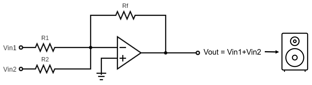
In signal summing (Figure 1) we take two (or more) signals and sum them as one. The summed signal will be a mixture of the the elements from the signals added together. The signal summation can happen in two ways:
- Electric summation: We can visualize this better if we imagine two wires or cables, each carrying a different signal, which we then join together. We call this electrical summing. Then, if we connect this cable into a speaker, it will reproduce the the signals altogether, as one. Nowadays, this form of summing can be made through your Digital audio Workstation (e.g., Cubase). Technically, this sum is little different than soldering the wires, but for our purpose of explaining signal sum, it will work perfectly.
- Acoustic summation: If we have two speakers, even though each of them is playing something different, we can hear both at the same time. And we can hear individual elements from both of them at the same time. This means that, in our ears and brains, we sum the signals acoustically. This happens specially in a stereo system.
The distinction between electric and acoustic summation is import to understand the pan law as we will see later.
 |
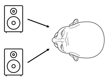 |
Figure 1. Left: Two mono signals (V1 and V2) with electrical summing, using a simple electronic circuit, giving Vout. The scheme represents an op-amp (operational amplifier; triangle) circuit of a so-called inverting amplifier. If all resistors are equal, i.e., R1=R2=Rf then we have Vout=V1+V2. Right: Stereo system with acoustic summation (in our brain).
Joining concepts
Let’s consider a stereo signal for the following examples. In other words, we have a pair of distinct signals. Our system may be mono or stereo, and the sum of our signals may be acoustic or electric. Let’s consider each of these combinations:
- Mono System, electric summing: We sum (two) signals before they travel to a single speaker which will reproduce the summed sound; which is a mix of both signals.
- Stereo System, electric summing: A stereo signal will be summed before traveling to both speakers. Each speaker will receive and reproduce the same joined signal, which is a mixture of both signals. In other words, there is no different information being played by either one. Both will reproduce the exact same summed signal, i.e., we hear a mono signal
- Mono System, acoustic summing: Not possible. For acoustic summing to happen, two sound sources are needed; a mono system is, by definition, made of one single speaker.
- Stereo System, acoustic summing: This is what happens when we play and listen to music. A music file has two channels which are completely separate (left and right). If we reproduce this file through a stereo system, each speaker will play one of these independent signals. It is summed acoustically in our brain when we listen to this music (acoustic sum of both signals).
(iii) Balance versus pan
A. Balance
A typical home stereo has a balance slider on the front. The idea is to set the balance control for a stereo track such that you hear equal volume from each speaker. This often isn’t necessary, but if you sit right next to one speaker and far away from another, it makes sense to use it. To achieve this, the volume of each channel is raised or lowered accordingly, but the mix of left and right in each speaker is unchanged. If we take the example of some music recorded with a guitar all the way to the right in the stereo field and a vocal all the way to the left and if we set the balance slider all the way to the right then we will only hear the guitar and no vocal (Figure 2).
B. Pan
The pan control works by splitting a single signal from the output of a fader into two signals (left and right), setting the position in the image by varying the level difference between left and right channels (Rumsey and McCormick, 2021).
For mono tracks, all pan knobs work the same way. Setting the mono pan control to the left will move the sound to the left speaker while setting it to the right will move the sound to the right speaker. It is also possible to position a sound somewhere between the center and the left speaker or the right speaker.
A stereo pan control gives us the capability to place the left and the right channels of the stereo track to any position we want in the stereo panorama, independent from one another. This requires two pan knobs, i.e., one for the left and one for the right channel. The pan control is taking some of one channel, moving it over to the other channel and spoiling the stereo experience.
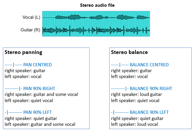
Figure 2. Panning and balancing for stereo tracks
In Cubase we have different panning modes:
- Mono panner. A mono audio track can be positioned anywhere in the stereo field.
- Stereo combined panner [here]. A stereo audio track has the ‘stereo panning‘ functionality and is similar to the stereo panning shown in Figure 2. With the stereo combined panner, the left and right pan controls are linked and keep their relative distance if you move them. It is available for channels with a stereo input and output configuration.
- Stereo balance panner [here]. A stereo output, group or audio track has the ‘stereo balance‘ functionality shown in Figure 2. The stereo balance panner allows you to control the balance between the left and right channels. It is activated by default.
- VST MultiPanner plug-in. This allows you to position any supported mono, stereo, or multi-channel sound source [here].
(iv) Decibel summary
I have explained the concept of decibels in great detail in a previous post [here]. Here, I will summarize and expand the concepts required to understand the pan law.
A. Definition of decibels for (root-)power quantities
Sound power  (a.k.a. acoustic power; Watts) is an example of a so-called power quantities. The level (
 ) for these quantities is specified as a ratio relative to a reference value:
![\[ \boxed{ \!\begin{aligned} L_{pq} = \textbf{10} log_{10} \left( \frac{P}{P_{ref}} \right) \end{aligned} } \]](https://skippystudio.nl/wp-content/ql-cache/quicklatex.com-827c924e994e885bf255656ed81097d2_l3.png "Rendered by QuickLaTeX.com")
If we talk about acoustic power then the normal reference level is  (i.e., 1 picowatt), which is the lowest sound persons of excellent hearing can discern. Note that some older books use a reference value of
If acoustic power (AP) is halved (i.e.,  ) then its level drops by 3dB:
![\[ \boxed{ \!\begin{aligned} L_{AP} &= 10 log_{10} \left( \frac{0.5*P}{P_{ref}} \right) \\ &= 10 log_{10} (0.5) + 10 log_{10} \left( \frac{P}{P_{ref}} \right) \\ &= \textbf{-3dB }+ 10 log_{10} \left( \frac{P}{P_{ref}} \right) \end{aligned} } \]](https://skippystudio.nl/wp-content/ql-cache/quicklatex.com-83001ac6ac66acc5048a9be2a0575875_l3.png "Rendered by QuickLaTeX.com")
Sound pressure ( ) level (SPL; Pa) and voltage (
 ) are examples of root-power quantities. Note that we use small letter for sound pressure while we use capital letter for sound power. For root-power-quantities, the level is specified as:
![\[ \boxed{ \!\begin{aligned} & L_{rpq} = \textbf{20} log_{10} \left( \frac{p}{p_{ref}} \right) \\ \end{aligned} } \]](https://skippystudio.nl/wp-content/ql-cache/quicklatex.com-fa428dfc6e2f5a865089ba71ab6fd237_l3.png "Rendered by QuickLaTeX.com")
If we consider sound pressure level (SPL) we see that halving the SPL (i.e.,  ) results in a level drop of
  :
:
![\[ \boxed{ \!\begin{aligned} L _{SPL} &= 20 log_{10} \left( \frac{0.5*p}{p_{ref}} \right) \\ &= 20 log_{10} (0.5) + 20 log_{10} \left( \frac{p}{p_{ref}} \right) \\ &= \textbf{-6dB} + 20 log_{10} \left( \frac{p}{p_{ref}} \right) \end{aligned} } \]](https://skippystudio.nl/wp-content/ql-cache/quicklatex.com-ee7ba7ce70f919568b63d1530da04eb1_l3.png "Rendered by QuickLaTeX.com")
B. Coherent and incoherent sound sources
One of the key concepts in acoustics is the difference between coherent and incoherent sound sources. Coherent sound sources are those that maintain a constant phase relationship with each other. This means that the waves emitted by these sources are synchronized in such a way that their peaks and troughs match up over time. Because of this synchronization, coherent sound waves can interfere with each other constructively and destructively. For example, if we play an sine tone of 500Hz from two speakers, then we have two coherent sound sources. Incoherent sound sources, on the other hand, do not maintain a constant phase relationship. The phase difference between their waves changes randomly over time. As a result, the interference effects are averaged out, and no clear interference pattern is produced. Incoherent sound sources tend to produce a more uniform sound field. For example, if we have two different signals (e.g., two sine waves of different frequencies, or two different instruments, or two different songs) then at certain moments the corresponding signals may cancel each other if they are completely out of phase (0 Pascal), or their level is doubled if they are perfectly in phase (+4 Pa). Since sound waves vary over time the combined magnitude constantly varies between 0 and 4 Pascals over time (Figure 3).

Figure 3. Summation of two incoherent signals (the source signals do not maintain a constant phase relationship). Figure copied from Siemens.
C. Amplification
Gain is the measure of how much an amplifier (triangle in Figure 1) “amplifies” the input signal (Figure 4). For example, if we have an input signal of 2 volt and an output of 50 volts, then the gain ( ) of the amplifier would be 25, i.e., the input signal increased by a factor of 25. Amplifier gain is simply the ratio of the output divided-by the input. Gain has no units as its a ratio.
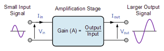
Figure 4. Amplification with gain of an input signal.  is current, =voltage. Figure copied from Electronics Tutorials.
There are three different kinds of amplifier gain which can be measured and these are: Voltage Gain ( ), Current Gain (
 ) and Power Gain
  ) depending upon the quantity being measured. Also note that Power (; Watt) = Voltage ()
  Current ().
![\[ \boxed{ \!\begin{aligned} A_{V} &= \frac{\text{Output Voltage}}{\text{Input Voltage}} = \frac{ V_\text{Out}} {V_\text{In}} \\ A_{I} &= \frac{\text{Output Current}}{\text{Input Current}} = \frac{ I_\text{Out}} {I_\text{In}} \\ A_{P} &= \frac{\text{Output Power}}{\text{Input Power}} = \frac{ P_\text{Out}} {P_\text{In}} = \frac{V_\text{Out} \times I_\text{Out}}{V_\text{In} \times I_\text{In}} = A_V \times A_I \\ \end{aligned} } \]](https://skippystudio.nl/wp-content/ql-cache/quicklatex.com-5c890551b11d8fec4642eb20a66eca16_l3.png "Rendered by QuickLaTeX.com")
If we double the voltage ( ) and double the current (), then the amplification
  , which is
  . For the pan law it is not necessary to understand or use these details (and it is even a bit more complex), but good to know.
D. Decibel levels with one speaker
Let us now assume that we have a single sound source (e.g., one speaker). Let us consider the sound pressure level:
![\[ \boxed{ \!\begin{aligned} L_{SPL} &= 20 log \frac{p_1}{p_0}\\ \end{aligned} } \]](https://skippystudio.nl/wp-content/ql-cache/quicklatex.com-177075d3e88b59327a8d26a83cd51dc8_l3.png "Rendered by QuickLaTeX.com")
The reference value  has been defined as
  (i.e., 0.00002 Pascal) because that is near the absolute threshold for a sound frequency of 1 kHz. Thus, a sound pressure of 2 Pa corresponds to
  .
.
If a signal is added to itself (mixed on two inputs at equal levels, e.g., a mixbus), then this will double the voltage giving a  increase (Figure 5). Note, that in this case the signals are, by definition, of equal amplitude and are in phase. Thus, these two signals are coherent (correlated).

Figure 5. Voltage, (acoustic) power, and sound pressure level (SPL). If we double the voltage ( by feeding two identical signals to a mix bus (audio source) then also the sound power level increases with 6dB (
 ; hence, 4 times increase in power ). Consequently, also the sound pressure level increases with 6dB corresponding to a doubling of the sound pressure . Figure modified from Don Davies, Eugene Patronis, Jr. (2006) Sound System Engineering. Third Edition. Elsevier Focal Press, Amsterdam.
Note that the four times increase in power (Figure 5) for a doubling of voltage does not only follow from the decibel calculations (see [here]) but also follows from the following relationships (note that for fixed  the current must double if the voltage is doubled):
![\[ \boxed{ \!\begin{aligned} \left. \begin{array}{r@{}l} P &= V \cdot I \\ V &= I \cdot R \rightarrow I =\frac{V}{R} \end{array} \right\rbrace \begin{array}{r@{}l} P =\frac{V^2}{R} \end{array} \right. \end{aligned} } \]](https://skippystudio.nl/wp-content/ql-cache/quicklatex.com-918350afc835f0d671412fb5b785c16c_l3.png "Rendered by QuickLaTeX.com")
Thus, we see that doubling gives a four times increase in .
E. Decibel levels with two speakers
(I). Summation of sound pressure levels for coherent signals
Suppose you measure the sound pressure level  in front of one speaker (at a certain fixed distance), and you get a reading of 100dB SPL. Next you add a second speaker that also produces a sound pressure of 100dB SPL (Figure 6). Also assume that the signals from both sources are coherent (correlated, identical). This will result in a 6dB increase in sound pressure.

Figure 6. At point x (assuming two coherent signals) you experience 100dB SPL from each speaker. The total sound pressure level at x will be  . Note: here we calculated the increase in SPL if the sound pressure doubles at point x. This situation is not the same as doubling the acoustic power (P) due to using two amplifiers/speakers (see Figure 9). Going from one to two amplifiers/speakers doubles the acoustic power, which is
  , which would gives a increase in SPL. Thus, doubling amplifiers/speakers does not double SPL because acoustic power
  . If speakers are very close then the level (for lower frequencies) might increase more than because of mutual coupling (see video later in this powerpoint).
Let us consider this situation very carefully. What are we doing here? We assumed that we somehow doubled the SOUND PRESSURE LEVEL, which is equivalent to an increase of 6dB as we know. Considering the 100dB SPL from a single speaker and a reference level of  gives
gives
![\[ \boxed{ \!\begin{aligned} 100dB &= L_{SPL} = 20 log \frac{p_1}{p_{ref}} = 20 log \frac{p_1}{20^{-6}} \\ p_1 &=2 Pascal \end{aligned} } \]](https://skippystudio.nl/wp-content/ql-cache/quicklatex.com-609a2422f4ebd161620265af5a4de642_l3.png "Rendered by QuickLaTeX.com")
If we add the second speaker that also produces a pressure of 2 Pascal at the same point, then in total a pressure of 4 Pascal is produced, which gives  .
.
How does this relate to the ACOUSTIC POWER () change? If a single speaker results in a sound pressure level of 100 dB SPL then the acoustic power level is also 100 dB due to the simple fact that (i.e.,  ) (see [here]).
Note also that acoustic power is equal to sound pressure level only for omnidirectional sources in free space at a distance of 0.2821 m from the source (see [here]). Since we are only interested in changes in acoustic power or sound pressure level, it is valid to consider this specific situation.
![\[ \boxed{ \!\begin{aligned} 100dB &= L_{AP} = 10 log \frac{P_1}{P_{ref}} = 10 log \frac{P_1}{10^{-12}} \\ P_1 &=0.01 \,\text{Watt} \end{aligned} } \]](https://skippystudio.nl/wp-content/ql-cache/quicklatex.com-9af46fd58d0afcba078b20db40dd5d86_l3.png "Rendered by QuickLaTeX.com")
Now, if we want to achieve a sound pressure level of 106 dB then by definition we have an acoustic power level of 106 dB. Thus, we have  , which gives
  . Consequently, as we have seen before, we need to quadrupole the power to achieve a level of
  .
.
Thus, to achieve a doubling in sound pressure (+6dB), the second speaker needs a power of 0.03 Watt in addition to the first speaker with a power of 0.01 Watt, giving a total of 0.04 Watt.
Note, that 0.01 Watt and 0.03 Watt correspond to 100 and 104.77 dB respectively (a total of 106 dB). Alternatively, we can take two speakers each having 0.02 Watt of power corresponding to 103.0103 dB. For addition of unequal levels see for example [here]. Figure 7 summarizes these calculations.
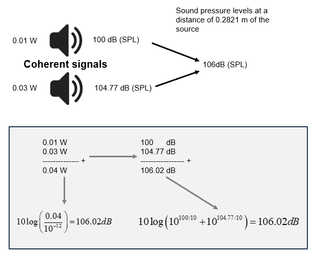
Figure 7. This figure summarizes the relation between acoustic power (), acoustic power level, and sound pressure levels (SPL) for coherent signals. The left side calculation directly converts 0.04W into decibels. The right side calculation shows how to adding the different sound pressure levels result in the same outcome. We have taken a reference level of  resulting in SPL reflecting the level above the reference of
  . The SPL is calculated at a distance of 0.2821 m from the source. See also [this] table.
(II). Summation of sound pressures (or voltages) for incoherent signals
For incoherent signals (i.e., music) we need to use the root mean square (RMS) pressure instead of simply summing two pressures. I have included this scenario for completeness, but it is not relevant for the pan law that, by definition, is about coherent signals. Thus we have:
![\[ \boxed{ \!\begin{aligned} p_{\text{rms}} = \sqrt{p_1^2 + p_2^2} \end{aligned} } \]](https://skippystudio.nl/wp-content/ql-cache/quicklatex.com-687fd6758d5adee327632ff5a9207d13_l3.png "Rendered by QuickLaTeX.com")
If we have two speakers with the same producing 100dB SPL each at point x (Figure 8) but with incoherent signals, then these levels add to 103dB instead of 106dB. We can easily derive this:
![\[ \boxed{ \!\begin{aligned} L_{SPL} &= 20 log \frac{p_1}{p_{ref}}\\ 100dB &= 20 log \frac{p_1}{20 \cdot 10^{-6}}\\ p_1 &= 2 Pa \end{aligned} } \]](https://skippystudio.nl/wp-content/ql-cache/quicklatex.com-4852b25960ac0bb6f70110e875369dd7_l3.png "Rendered by QuickLaTeX.com")
Thus  is also 2Pa. Since
  we have a total RMS pressure at point x of
  . This corresponds to an increase of 3dB compared to speaker 1:
![\[ \boxed{ \!\begin{aligned} L_{SPL} &= 20 log \frac{\sqrt{2p_1^2}}{p_1}\\ &= 20 log \frac{\sqrt{2} p_1}{p_1}\\ &= 20 log \sqrt2 = 3dB \end{aligned} } \]](https://skippystudio.nl/wp-content/ql-cache/quicklatex.com-77cd67ad943be25bb48f60d5b38e9948_l3.png "Rendered by QuickLaTeX.com")

Figure 8. At point x (assuming two incoherent signals) you experience 100dB SPL from each speaker. The total sound pressure level at x will be  .
.
F. The signal chain
In the previous sections we considered different situations to explain how levels increase if voltage, power, or pressure increases. Now, we can consider a complete signal chain (Figure 9) in order to put things together. Note that this signal chain is a simplification of a real signal chain (e.g., it does not differentiate between a pre-amplifier (small signal amplifier) and power amplifier (see [here]). In addition, we do not make explicit if voltage and/or current is amplified. Nor do we make a difference between the analog and digital domain. Nevertheless, this simplification is sufficient to explain what is going on in terms of levels.
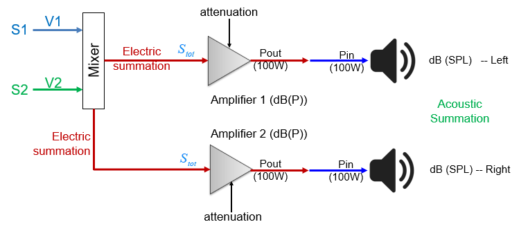
Figure 9. Signal chain. The signal chain starts with a mixer (analog or DAW). The mixer results in an electric summation of multiple signals (here S1 and S2) that have a certain amplitude (Voltage; ). The total signal ( ) is amplified. Typically, this signal is first pre-amplified to result in a larger signal that is input to the power amplifier, which feeds the speakers. Note, in this figure we have denoted the maximum power of the amplifier (100W) and maximum input of the speaker. However, these wattages are not further relevant for our discussion. Also note that the (pre)amplifier can be attenuated (i.e., no attenuation=1 gives full power, which is 0dB). In this figure the total signal
  is fed to two identical amplifiers and speakers (e.g., active monitor speakers).
Let us go over the signal chain step by step. We only consider coherent signals. First we consider a single amplifier and speaker, thus neglecting the lower branch of the signal chain.
- If
 the electric summation results in a 6dB (2-fold) voltage increase:
  .
. - We have seen that a 6dB voltage increase results in a 6dB (4-fold) increase in acoustic power level (attenuation =1).
- In turn, this results in a 6dB (2-fold) increase in sound pressure level (SPL; acoustic summation).
 the electric summation results in a 6dB (2-fold) voltage increase:
  .
.Here and in the next, we again assumed an omnidirectional source (speaker) in free space and at SPL measurements at a distance of 0.2821 m from the source. Now, let us consider both branches of the signal chain (both amplifiers and speakers):
- We assume that the same signal
 is fed into both amplifiers.
 - Since we double the number of amplifiers, we double the acoustic power, which gives a level increase of
 .
. - In turn, this results in a 3dB (
 -fold) increase in sound pressure level (SPL; acoustic summation).
 .
. -fold) increase in sound pressure level (SPL; acoustic summation).
It might seem confusing that the electric summation results in a SPL increase of 6dB but adding the speaker results in only a SPL increase of 3dB. But realize the following:
- Doubling the voltage does quadruple (6dB) the power (e.g., going from 1 to 4 Watt), resulting in a doubling of sound pressure (6dB)
- When we add the second amplifier with the same input signal then the power of this second amplifier also increased from 1 to 4 Watt (6dB).
- Overall, the power has doubled from 4 Watt (single amplifier) to 8 Watt (two amplifiers), thus an increase of 3dB. Hence, the sound pressure increases with ), which is 3dB.
- Since doubling voltage results in 6dB SPL increase (e.g., going from 1 to 4 micro Pascal) for a single speaker, one may think that one also doubles the total sound pressure to 8 micro Pascal (6dB) when adding a second speaker. This, however, is not true. By adding a second amplifier/speaker we will not get 8 micro Pascal of pressure. Double power (4 to 8 Watt) does not translate to double pressure due to the fact that
 . In order to get a doubling of sound pressure we would need to add an additional 2 amplifier/speakers.
In the Excel sheet below you can inspect these calculations in more detail and make changes to determine its effect.
2. Pan law
There are several different pan laws in common use (in DAWs and analog consoles) that determine the relationship between the control rotation and the inter‑channel level difference. These laws generally follow a sine/cosine relationship as I will explain later. An important aspect of the pan law is the actual output level from each channel when the pan pot is at the center position. Commonly, for this center position, 3, 4.5 or 6dB of attenuation is applied, which I will explain below.
(i) General explanation
A typical pan law ensures a roughly constant perceived level of sound as the signal is panned from left to right in stereo.
When a signal is panned centrally, the same signal will be output identically on both the left and right channels. If you pan this signal from the extreme left channel through the center and then onto the extreme right channel, it will sound as if the level rises as it passes through the center. (the signal is acoustically summed). This is shown in Figure 10. Let me walk you through this figure:
- On the left side we have a mono audio file of a guitar (in Cubase).
- The fader for this audio file is set to 0dB. The audio is panned fully to the left (blue bar on top of fader).
- Let’s suppose that the level of this audio file is -5 dBFS (yellow line). This level will then be shown by the metering on the mono fader. To avoid confusion, note that the 0dB of the fader is not at the same height as the 0dBFS in the metering.
- This track is routed to the stereo output. Therefore, on the left channel of the stereo out we will also see a level of -5 dBFS.
- The stereo out is send to your amplifier resulting in a level of, say, 100 dB SPL from the left speaker. This is the level that you will perceive.
- Next, we change the situation: we pan the mono guitar track centrally (middle yellow fader; pan denotes ‘c’).
- On the yellow mono fader we will still see -5 dBFS. On the red Stereo Out fader we will see -5 dBFS both on the left and right channel.
- Consequently, both the left and right speaker will produce, say, 100 dB SPL. This creates a phantom center.
- Now, due to acoustic summation, you will perceive a level of 103 dB. Thus, the level has increased with 3dB (
 increase in sound pressure). Note that we are listening to two coherent sound sources, i.e., you are listening to the same signal (guitar) from the left and right speaker.
 - Thus, if you pan from fully left to fully right then you will first hear an increase in sound level, and then a reduction in sound level until you reached 100 dB SPL again.
- This is what we call the 0 dB stereo pan law because there is no correction made to the center level.
 increase in sound pressure). Note that we are listening to two
 In theory you should be able to easily check this in your DAW (make sure to set the stereo pan law to 0 dB) and use a dB meter to measure the level. However, I found it quite difficult to get accurate measures with my dB meter to confirm an increase of 3dB (due to room acoustic, etc).
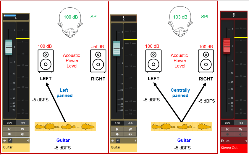
Figure 10. Panning from left to center doubles the acoustic power (note the pan indicator above the fader), which increases the perceived sound level by 3dB (for the 0 dB pan law). The yellow fader represents a mono signal (guitar). The red fader represents the stereo output. -inf dB indicates minus infinity, i.e., no sound. Note that we assume that the SPL equals the acoustic power level, which is only true for an omnidirectional source (speaker) in free space and at SPL measurements at a distance of 0.2821 m from the source.
To make this part of the story complete, consider the situation in Figure 11. Here we have two mono tracks that are panned to the center. Both tracks contain exactly the same guitar audio file (coherent sound sources) with a level of -5 dBFS. Thus each mono track contributes -5 dBFS to the left and right channel of the Stereo Out. Stated otherwise, the left channel receives -5 dBFS from the first mono track and -5 dBFS from the second mono track. This results in electrical summation (Volts) on the left channel, which also gives an increase in 6 dB (i.e., +1 dBFS, which is not a problem for the internal 31 bit floating point processing by the DAW). Also on the right channel of the Stereo Out we will see +1 dBFS. As a consequence, due to the electrical summation, we get a level of 106 dB of acoustic power (6 dB increase for single speaker). The listener now perceives a level as 109 dB (acoustic summation) given that we use the 0 dB pan law. This can be interpreted as going from 1 to 2 speakers (doubling the power), or having two speakers and going from 1 to 2 mono channels.
Note:
- A mono down mix of the Stereo Out channel is also equivalent to a electrical summation, resulting in a 6dB increase in level.
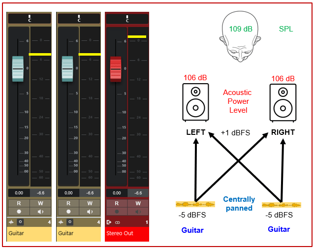
Figure 11. Acoustic and electrical summation (see level of yellow bar) in case of the 0 dB stereo pan law. Note that we assume that the SPL equals the acoustic power level, which is only true for an omnidirectional source (speaker) in free space and at SPL measurements at a distance of 0.2821 m from the source.
(ii) The 0dB, -3dB, -4.5dB, and -6 dB pan laws
In Cubase, other DAWs, and analog consoles, you may encounter different pan-laws. In Cubase we have the 0dB, -3dB, -4.5dB, and -6 dB pan laws. In addition, Cubase also provides an ‘equal power’ pan law to which I will come back to later. If you understand Figure 10 and Figure 11 then you should have no difficulties in understanding all of these pan laws. I explain these four pan-laws in slightly simplified Figures 12 to 15:
- The left panel shows one mono audio signal (S1) panned to the left speaker
- The right panel shows the same signal but now panned centrally to both speakers. Thus, we have identical (coherent) signals for speaker 1 and 2.
- The green arrows and text demonstrate the effect of a mono down mix.
- The text above the speakers in the right panel denote the effect of the acoustic summation.
- The caption of each figure describes the specific properties of each pan law.
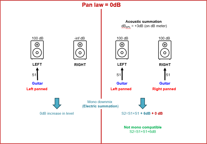
Figure 12. The 0 dB pan law. If we down mix the mono signal on the left (or set our monitor controller to mono), then there will be no change of level since no summation is applied (we only have a single signal). If we pan our guitar in the center, we will have the signal S1 on both speakers. If we downmix this stereo signal then we effectively apply an electrical summation giving the mono signal S2=S1+S1. This gives a signal (voltage) increase of +6dB (S1+S1+6dB); bold blue). This is not compensated by the current pan law (0 dB; bold red). Consequently, this pan law is not mono compatible since we get an increase in audio level. The acoustic summation will result in a 3dB increase in perceived level (SPL), which can also be measured by a the decibel meter. Thus, if we pan the guitar from left to center we will perceive a volume increase. Further panning to the far right will decrease the volume level again with 3dB.
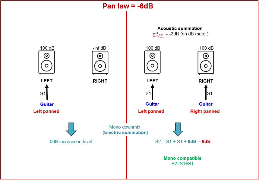
Figure 13. The 6 dB pan law. If we downmix this stereo signal then we effectively apply an electrical summation giving the mono signal S2=S1+S1. This gives a signal (voltage) increase of +6dB (S1+S1+6dB); bold blue). This is compensated by the current pan law (6 dB; bold red). Consequently, this pan law is mono compatible since we do not get an increase in audio level. The 6dB attenuation of the pan law results in a decrease in perceived level of the centrally panned signal by 3dB . Thus, if we pan the guitar from left to center we will perceive a volume decrease. Further panning to the far right will increase the volume level again with 3dB.
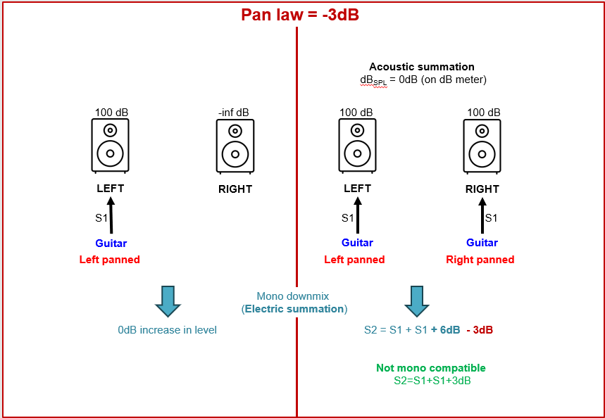
Figure 14. The 3 dB pan law. If we downmix this stereo signal then we effectively apply an electrical summation giving the mono signal S2=S1+S1. This gives a signal (voltage) increase of +6dB (S1+S1+6dB); bold blue). This is compensated by the current pan law (3 dB; bold red). Consequently, this pan law is not mono compatible since we do not get an increase in audio level of 3dB. The 3dB attenuation of the pan law results in a constant perceived level of the centrally panned signal . Thus, if we pan the guitar from left to center we will not perceive a volume increase or decrease.
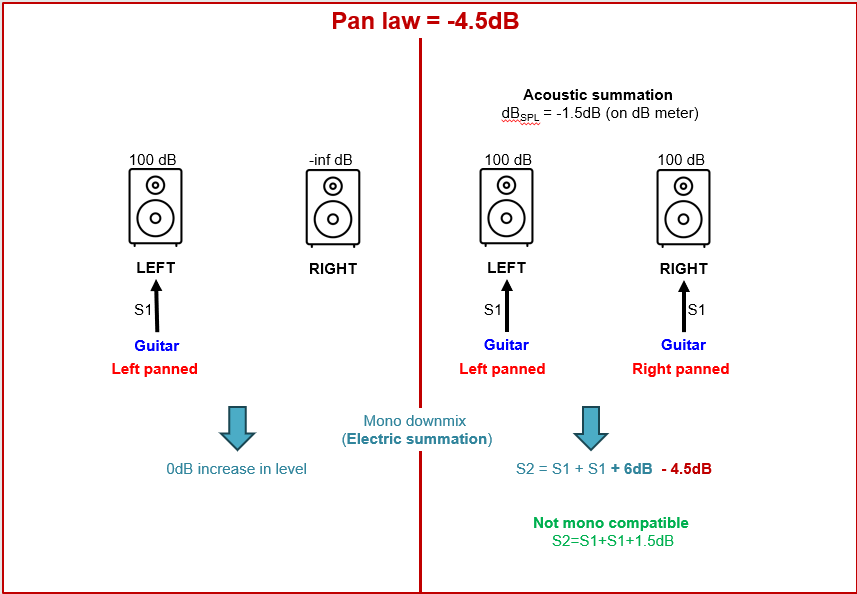
Figure 15. The 4.5 dB pan law. If we downmix this stereo signal then we effectively apply an electrical summation giving the mono signal S2=S1+S1. This gives a signal (voltage) increase of +6dB (S1+S1+6dB); bold blue). This is compensated by the current pan law (4.5 dB; bold red). Consequently, this pan law is not mono compatible since we do not get an increase in audio level of 1.5dB. The 4.5dB attenuation of the pan law results in a decrease in perceived level of the centrally panned signal by 1.5dB . Thus, if we pan the guitar from left to center we will perceive a volume decrease. Further panning to the far right will increase the volume level again with 1.5.
We see that only the 6dB pan-law is mono compatible, which is important in certain applications. However, this gives a reduction of level (3dB) for the listener; it will give a ‘gap’ in the center signal. The 3dB pan law is ideal from the listener perspective since this gives no change in signal level. However, this law is not mono compatible and results in a +3dB increase in level for a mono down mix. For these reasons, the 4.5dB pan law was introduced as a compromise between the -3dB and -6dB pan laws. This pan law gives a slight increase of +1.5dB in the mono down mix and a slight decrease of level of -1.5dB as perceived by the listener. Both are hardly audible.
(iii) Equal power pan law
The 3dB pan law is generally referred to as Equal Power law, meaning that the power of the signal (i.e., perceived level) remains the same, regardless of the pan setting. However, mysteriously, in Cubase we have a 3dB and Equal Power pan law. This is not explained in the Cubase documentation but I suspect it has to do with the linear versus constant power panning that I explain below.
When is the pan law relevant?
The actual panning law only really becomes significant when a source is being actively panned (using automation) across the soundstage and you want your audience to perceive the source as remaining at a constant level as it moves around. For any given static pan position you have to balance the source in the mix accordingly, and if you change the pan position you’ll inevitably also change the relative level of that source slightly and so will probably have to tweak the source level to maintain the same overall mix balance.
The -6dB option is there to cater for traditional broadcast and when output is summed to mono. Summing to mono would create a 6dB swell in the center due to the summed stereo output of incoherent sources. In stereo, the center channel would be perceived as 3dB higher than the left and right channels but in mono, the overall summed signal will sound even. So, broadcast desks use a -6dB attenuation
From SoundOnSound:
Why the different options? In systems where mono compatibility is critically important — such as in broadcast environments — it makes sense to ensure that the signal level of a source doesn’t vary as it is panned across the sound stage. When panned centrally, the input signal is obviously sent to both output channels, and when summed to mono those two channels are added together. Summing two identical signals electrically results in a 6dB increase in level, so to maintain a constant derived mono signal level regardless of pan position, the center point of the pan pot needs to attenuate both outputs by 6dB relative to the extreme edge positions. This is called a constant‑voltage law.
Some systems achieve this level variation by passing the input signal unchanged when panned fully to one side or the other, but attenuate it progressively as the pan nears the center. Others increase the signal gain as the input is panned towards the edges, and some use a combination of both techniques. There are advantages and disadvantages of each approach, but the important aspect is that when panned centrally, the level at both outputs is reduced relative to the level when panned fully to one side.
When listening to stereo speakers their outputs combine acoustically, not electrically, and this implies that a different attenuation amount is required. When reproducing the same signal from both speakers, the perceived level increases by only about 3dB compared with the same signal from one speaker only. So to maintain a constant perceived level as the pan pot is rotated, the center position attenuation needs to be just 3dB rather than 6dB. This is called a constant‑power law.
The last option is a compromise which splits the difference. This led to most modern analogue consoles with a -4.5dB center attenuation. For someone listening in mono, panning a source across the sound stage using this compromise law results in a barely noticeable 1.5dB ‘bulge’ around the central position. A stereo listener would hear a similarly marginal drop in level across the center.
The pan laws are inherently a compromise between optimizing the mono and optimizing the stereo. So if you want to pan a single source from hard left to hard right, and have it sound like it’s at the same level all the way across while listening in stereo, the panning law has to attenuate the level as it moves towards the middle, and then allow it to return to it’s normal level at the other side. And the amount of attenuation in the center needs to be 3dB to compensate accurately for the acoustic summation effect. But, if you watched a mono VU meter when you did that — or listening to the mono sum — you’d see that the signal level went up by 3dB in the middle because the electrical summation is +6 for equal sources (-3dB center pan attenuation +6dB from matched channel boost = +3dB overall).
Linear and constant power panning
Now we understand the pan laws, we are left with one other aspect to be addressed. A typical two-speaker stereo setup is depicted in Figure 16. The speakers are placed symmetrically at 45-degree angles, and equidistant to the listener. When panning from left to center to right, the level of the left and right channel (speaker) will change. When panned fully left, the level on the right channel will be zero. When panned fully right, the level of the left channel will be zero. The level of the center (mono downmix or acoustic summation) depends on the pan law chosen. The question is how exactly the level changes if we pan from left to right. In other words, how do the level curves of the level and right channel look like?
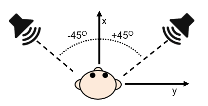
Figure 16. Typical two-speaker stereo setup.
An example of a level curves is shown in Figure 17. We see that the right speaker starts at gain=0 (no volume) and increases linearly until it reaches gain=1 (maximum level) when panned fully to the right. The total gain of the stereo channel remains unchanged (gain=1) across the full pan range. In fact, this linear panner corresponds to the 6dB pan law. Since the total gain is constant, the change in amplitude level  . In other words, the mono downmix will not change level as we have seen before. However, the power does change across the pan range, i.e.,
  . At the center, we have gain=0.5 for the left and right channel which gives
  . Thus, we experience a drop in level when panning from left to right. See Excel sheet for the cross-fade calculations for all pan laws.
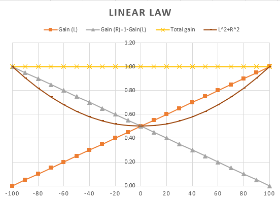
Figure 17. Linear panning (-6dB law). The gains for the left and right speaker add up to 1 (yellow line) resulting in a constant gain across the pan range. The acoustic power (brown line) drops with 10log(0.5)=3dB at the center. The x-axis denotes the panning from left (-100) to center (0) to right (+100). The y-axis denotes the amount of gain (<=1) applied to the left and right channel and the resulting total gain and power.
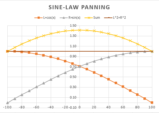
Figure 18. Sine law panning (-3dB law). This pan law has constant power across the pan range (i.e., no change in acoustic summation; brown line), but the amplitude goes up by 20log(1.41)=3dB at the center (yellow line). The x-axis denotes the panning from left (-100) to center (0) to right (+100). The y-axis denotes the amount of gain (<=1) applied to the left and right channel and the resulting total gain and power.
Videos
References
- Mark Buttler
- Processing Stereo Audio Files (SoundOnSound)
- What pan law setting should I use? (SoundOnSound)
- http://www.rs-met.com/tutorials.html (RS-MET; Linear and constant power pan rules)
- https://www.cs.cmu.edu/~music/icm-online/readings/panlaws/ (Introduction to Computer Music; Carnegie Mellon University)
- Stereophonic Amplitude-Panning: A Derivation of the ‘Tangent Law (DSPrelated.com)
- Pan Laws and Pan Curves (DAW comparison)
- What is a decibel?
- Martin, W.H. (1923) The Transmission Unit and Telephone Transmission Reference Systems. The Bell System Technical Journal, 3(3), 400
- Martin, W.H. (1929) Decibel — The Name for the Transmission Unit. The Bell System Technical Journal, 8(1) ,1
- Engineering at Alberta (Open Education Resources; Sound Power Level and Sound Pressure)
